Converting an old lighting track is not simply a matter of removing one rail and attaching another. The process requires careful inspection, accurate measurements, and a realistic understanding of the existing electrical system. This guide explains How to convert a traditional track to a magnetic system? It focuses on compatibility, installation planning, lighting performance, and long-term reliability.
Lighting designer and author Randall Whitehead has said, “Lighting is one of the most important elements in a space.” His observation is especially relevant during a track conversion. A magnetic system can create a cleaner ceiling line, sharper beam control, and easier fixture repositioning. Yet appearance should not lead the decision. The old track may hide loose wiring, weak mounting points, or a transformer that cannot support the new system.
Start with the details. Photograph the existing connections. Measure the track length. Check the ceiling material and circuit load. Then compare the magnetic rail’s voltage, driver location, connector type, and fixture capacity. A certified electrician should verify the wiring before power is restored. Small mistakes can cause flickering, overheating, or expensive ceiling repairs.
There is no universal conversion kit. Some installations need new drivers, adapters, or a completely different mounting base. That can be inconvenient. It may also reveal that replacing the whole circuit is safer than adapting every component. This guide keeps that possibility visible, because a visually simple upgrade can involve hidden technical compromises. The goal is not merely a modern track. It is a stable, serviceable, and properly engineered magnetic lighting system.
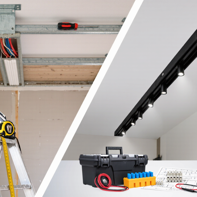
Traditional track and magnetic systems may look similar, but they use different electrical designs. A traditional track often carries line voltage directly to each fixture. A magnetic system commonly uses a low-voltage driver and magnetic contacts. The physical resemblance can cause expensive mistakes.
Check the voltage first.
Never connect a magnetic fixture to a traditional track without a purpose-built conversion method. The rail profile, conductor layout, polarity, mounting depth, and load rating must all match. A suitable adapter is not merely a mechanical clip. It must provide correct electrical isolation and stable contact. Poor alignment can create flickering, heat, or loose fittings.
Measure twice.
In real installations, compatibility reviews should include the driver location, cable size, dimming method, and total wattage. A 24-volt rail may need a driver that supports the selected dimmer. Some drivers also require ventilation above the ceiling. That detail is easy to miss. I have seen layouts that looked perfect on paper but failed after several fixtures were added. The planned load was acceptable, yet the dimming system was not. This is why testing one rail section with one fixture can reveal problems early. Keep installation records, product specifications, and test results together. A qualified electrician should verify the circuit and local requirements before energizing the system. Different regions use different voltage and safety rules, so online assumptions are unreliable.
A magnetic system begins with the track rail. It holds the magnetic channel and carries low-voltage power. Inside, copper conductors sit beside the magnetic strip. These parts must align correctly for stable contact and safe operation. The rail may be recessed, surface-mounted, or suspended. Each option changes the ceiling detail and installation workload.
The power supply is another essential component. It converts household voltage into the lower voltage required by the lighting modules. A suitable driver must match the system’s voltage, wattage, and dimming method. Poor matching can cause flickering, heat, or reduced service life. I always check the driver’s reserve capacity, not only the lamp’s listed wattage. Small details matter.
Lighting modules attach through magnetic adapters or mechanical locking points. Common forms include spotlights, linear bars, and adjustable heads. Connectors join track sections and transfer power around corners. End caps protect exposed ends and improve the finished appearance. Mounting clips, suspension wires, and insulation barriers support different ceiling conditions. Traditional track systems often rely on visible mechanical adapters, while magnetic systems create a cleaner transition. That advantage is real, but not automatic. Dust, weak alignment, or overloaded circuits can still create problems. A practical inspection includes firm module contact, hidden cable routes, accurate polarity, and secure ceiling anchors. When upgrading an existing track, measure the opening carefully. Old dimensions may not match new components.
| System Area | Traditional Track Solution | Magnetic System Component | Primary Function | Typical Technical Characteristics | Key Selection Considerations |
|---|---|---|---|---|---|
| Load Support | Steel rail, profile rail, or roller track | Magnetic guideway or linear motor rail | Defines the travel path and supports the moving carriage. | Usually consists of a precisely aligned structural rail, magnetic elements, and a carriage interface. | Rated load, rail straightness, mounting stiffness, thermal expansion, and allowable travel length. |
| Propulsion | Belt, chain, rack-and-pinion, or lead screw | Linear motor, generally iron-core or ironless | Produces direct linear thrust without a mechanical transmission between motor and carriage. | Thrust depends on motor design, current, cooling, duty cycle, and air gap; speed and acceleration are application-specific. | Continuous force, peak force, acceleration, heat dissipation, cogging, and required positioning performance. |
| Magnetic Field Generation | Not normally required for mechanical track motion | Permanent-magnet array and motor coil assembly | Creates the electromagnetic interaction that generates motion. | Permanent magnets commonly use rare-earth magnetic materials; coils use insulated copper conductors. | Magnetic force, demagnetization resistance, operating temperature, magnetic leakage, and nearby sensitive equipment. |
| Carriage Guidance | Wheels, bearings, or recirculating rolling elements | Precision linear bearings, air bearings, or magnetic guidance elements | Constrains unwanted lateral and vertical movement while allowing travel along the axis. | Rolling guidance requires preload and lubrication; air or magnetic guidance can reduce contact friction but requires controlled operating conditions. | Stiffness, straightness, vibration, contamination, maintenance access, and permissible angular error. |
| Position Feedback | Limit switches, rotary encoders, or mechanical stops | Linear encoder or linear position sensor | Measures the carriage position for closed-loop motion control. | Optical and magnetic linear scales are common; resolution, accuracy, repeatability, and signal format vary by design. | Required accuracy, resolution, interpolation, measuring length, contamination protection, and thermal compensation. |
| Motion Control | Motor controller with mechanical transmission compensation | Servo drive and motion controller | Regulates current, velocity, acceleration, position, and synchronization. | Uses feedback loops, current control, trajectory planning, and protection functions such as overcurrent and overtemperature monitoring. | Motor compatibility, control-loop bandwidth, feedback interface, network protocol, tuning tools, and software integration. |
| Power Delivery | Fixed motor cable or drag-chain cable routing | Flexible power and feedback cable system | Transfers electrical power and sensor signals to moving components. | Cable selection depends on current, voltage, bending radius, flex cycles, shielding, and travel distance. | Continuous-flex rating, electromagnetic compatibility, heat generation, cable carrier size, and connector protection. |
| Thermal Management | Usually limited to bearing and motor heat management | Passive heat sink, forced-air cooling, or liquid cooling | Removes heat from coils and drive electronics to maintain performance and service life. | Motor force decreases or operating limits may change as coil temperature rises. | Duty cycle, ambient temperature, enclosure conditions, cooling capacity, noise, and condensation control. |
| Cable and Hose Management | Cable chain, festoon, or fixed routing | Energy chain or guided flexible loop | Protects moving cables, cooling lines, and pneumatic hoses during repeated travel. | Must accommodate minimum bend radius, travel speed, acceleration, and the number of flexing cycles. | Cable fill ratio, unsupported length, debris protection, serviceability, and routing clearance. |
| Safety and Limiting | Mechanical end stops, limit switches, and emergency stops | Limit sensors, end stops, safe torque removal, and controlled braking | Prevents overtravel and reduces risks caused by unexpected motion or power loss. | Safety architecture should include independent stopping or energy-isolation methods where required by the risk assessment. | Stopping distance, stored energy, emergency-stop category, guarding, access points, and applicable machinery standards. |
| Mounting and Alignment | Rail supports with mechanical adjustment points | Precision base, datum surfaces, shims, and alignment references | Maintains the designed air gap, parallelism, flatness, and sensor relationship. | Alignment errors can increase vibration, reduce accuracy, raise heat, or cause contact between moving parts. | Base stiffness, installation tolerance, measurement method, thermal movement, and access for adjustment. |
| Maintenance | Lubrication, belt or chain tensioning, and bearing replacement | Inspection of magnets, sensors, guide surfaces, cables, cooling, and alignment | Preserves motion accuracy, thermal performance, and operational reliability. | Magnetic systems reduce mechanical transmission wear but still require cleaning, inspection, calibration, and electrical checks. | Contamination level, access time, inspection intervals, spare parts, calibration requirements, and technician training. |
Begin with a detailed survey of the existing track. Measure total length, curve radius, gradient, and spacing between parallel lines. Record every uneven joint and worn section. Small errors can become serious alignment problems.
Use a flexible measuring tape for straight sections and a radius gauge for curves. Mark bridge entrances, tunnel portals, switches, and maintenance gaps. Measure vertical clearance above the rail. Magnetic components may require more space than traditional hardware. Leave room.
I learned this the hard way. My first measurement ignored a slight curve near a platform. The conversion later required a costly adjustment. Measure twice, then create a scaled track plan. Include power supplies, control units, access points, and emergency isolation sections. Check whether existing vehicles can operate with the new magnetic system. Their weight, underside clearance, and guidance method matter.
Plan the conversion in small test zones. A short straight section can reveal alignment, noise, control, and stopping issues before full installation. Keep written records of measurements and changes. Photograph hidden joints before covering them. Allow extra budget for transition parts and unexpected repairs. A perfect plan rarely survives the first physical test, so build in time for revision.
Converting a traditional track into a magnetic system begins with accurate measurements. Check the existing ceiling opening, rail length, power feed, and mounting surface. A magnetic rail may look slim, but its power supply needs safe clearance and proper ventilation. Turn off the circuit before removing any components. A qualified electrician should verify wiring and local electrical requirements.
Mark the rail centerline with a laser or chalk line. Secure the rail to solid framing, not only to plasterboard. Use suitable anchors when framing is unavailable. Leave clean access near the power entry point. Connect the adapter only after confirming voltage, polarity, and system compatibility. Loose terminals can create heat and flickering. Small details matter.
Slide each fixture gently into the rail. Do not force a connector that feels tight. Position spotlights over work surfaces, then adjust their beam angles after installation. I once placed several fixtures too close to a wall, creating harsh scallops. Repositioning them improved the room, but it cost extra time. That mistake still influences my layout checks. Test every fixture before closing covers, and inspect the rail for movement, noise, or uneven alignment. A neat installation should also remain serviceable.
After converting a traditional track into a magnetic system, testing must begin with the power isolated. I inspect rail alignment, fasteners, sensors, coils, and cable insulation. A 1 mm gap error can create uneven lift or unwanted vibration. Small gaps matter. I record the measured air gap at several points, not only at the entrance and exit.
During commissioning, I increase power in controlled steps and monitor current, temperature, vibration, and stopping distance. The International Energy Agency reports that rail carries about 8% of global passenger travel but uses roughly 2% of transport energy, so efficiency testing deserves careful attention. I compare actual energy consumption with the design estimate. If readings drift, I stop and investigate instead of compensating with higher power. That shortcut may hide a mechanical fault.
Maintenance should follow a written inspection schedule based on operating hours and environmental exposure. The UIC safety database shows that reliable reporting and standardized investigation are central to railway risk control. I clean sensor surfaces, check connector torque, verify emergency shutdown circuits, and recalibrate position sensors after unusual vibration. ISO 13849-1 also supports validating safety-related control functions before service. My early test records were too brief; that was a mistake. Now, every adjustment includes date, location, measured value, technician, and reason. Trend charts often reveal deterioration before passengers or operators notice it.
The chart shows a practical maintenance schedule for a completed traditional track-to-magnetic system. Shorter intervals are used for visual inspection and functional testing, while insulation testing and calibration are scheduled less frequently.
Usually, no. Traditional tracks may carry line voltage, while magnetic systems often use low-voltage drivers. Direct connection can cause flickering, heat, or equipment damage.
Check voltage, rail profile, conductor layout, polarity, mounting depth, and load rating. Every detail matters.
No. The adapter must provide electrical isolation and stable contact. A loose fit can create heat or intermittent operation.
Record its length, curves, gradients, spacing, joints, and vertical clearance. Use a flexible tape for straight sections and a radius gauge for curves.
Bridges, tunnel entrances, switches, maintenance gaps, and worn joints can affect alignment. Magnetic parts may also need extra space above the track.
A small test zone is safer. Test one straight section with one fixture or vehicle before expanding. This can expose control, noise, alignment, and stopping problems early.
Begin with power isolated. Inspect alignment, fasteners, sensors, coils, and cable insulation. Then increase power gradually while monitoring temperature, current, vibration, and stopping distance.
Record the date, location, measured value, technician, and reason for every adjustment. Trend charts can reveal deterioration early. My first records were too brief.
A qualified electrician or competent safety professional should verify circuits, insulation, controls, and local requirements. Regional voltage rules differ, so online assumptions are unreliable.
This guide explains How to convert a traditional track to a magnetic system? by first examining compatibility, dimensions, wiring, and installation conditions. It introduces the main components, including magnetic rails, power supplies, adapters, connectors, and compatible fixtures, helping readers understand how each part works together. Careful measurement of the existing track, ceiling layout, load requirements, and electrical connections is essential for creating a safe and practical conversion plan.
The installation process covers removing or adapting the traditional track, positioning the magnetic rails, connecting the power system, and securing the fixtures correctly. After installation, the system should be tested for stable power delivery, reliable fixture movement, alignment, and heat management. The guide also highlights adjustment and maintenance practices, such as checking connections, cleaning the rails, inspecting fixtures, and resolving loose or uneven components. With thoughtful planning and regular inspection, a converted magnetic lighting system can provide flexible positioning, clean appearance, and dependable long-term performance.
Ledic Lighting